
Study on the Mechanism of Thickness Tolerance and Surface Roughness of Aluminum Discs in Enhancing Thermal Conductivity Efficiency
Abstract
Due to its excellent thermal conductivity (thermal conductivity of pure aluminum, λ≈237W/(m・K)), aluminum discs are widely used in electronic heat sinks, cookware heating plates, new energy battery thermal management, and other fields. Their thermal conductivity efficiency directly determines the performance stability of end products (such as chip temperature rise control and heating uniformity of cookware). Based on Fourier’s Law of Heat Conduction and the theory of interface thermal resistance, this paper systematically analyzes the influence mechanisms of thickness tolerance (usually controlled within ±0.02~±0.1mm) and surface roughness (Ra=0.05~1.0μm) of aluminum discs on thermal conductivity efficiency: Thickness tolerance affects heat flux uniformity by regulating the consistency of heat conduction paths and the distribution of interface contact pressure; surface roughness dominates the magnitude of interface thermal resistance by changing the actual contact area and the state of the surface oxide film. Combined with GB/T 3880.3 (Thickness Tolerance Standard), GB/T 1031 (Surface Roughness Standard), and finite element analysis (FEA) simulation data, the contribution of these two parameters to thermal conductivity efficiency is quantified (optimizing thickness tolerance can improve thermal conductivity efficiency by 8%~15%, while optimizing surface roughness can improve it by 12%~20%). A scenario-specific collaborative optimization strategy for parameters is proposed, and its effectiveness is verified through case studies of electronic heat sinks and cookware, providing theoretical and engineering basis for improving the thermal conductivity of aluminum discs.
HW-A. Introduction
In heat transfer systems, aluminum discs serve as core heat-conducting components, and their thermal conductivity efficiency is affected by both “intrinsic thermal conductivity of materials” and “geometric/surface states”. When the material is fixed (e.g., 1060 pure aluminum, 6061 aluminum alloy), geometric parameters (thickness tolerance) and surface states (roughness) become key regulatory factors. According to a survey by the China Electronic Components Industry Association, in 2024, 28% of heat conduction failures in heat sinks in China were caused by excessive thickness tolerance of aluminum discs (>±0.05mm), and 35% of interface thermal resistance exceedances were caused by improper surface roughness (Ra>0.8μm). For example, if the thickness tolerance of aluminum discs used in CPU heat sinks increases from ±0.02mm to ±0.1mm, the chip temperature rise will increase by 8~12℃; if the Ra of aluminum discs for cookware heating plates increases from 0.2μm to 1.0μm, the deviation of heating uniformity will expand to more than 15%. Therefore, clarifying the mechanism of action of thickness tolerance and surface roughness is of great engineering value for improving the thermal conductivity efficiency of aluminum discs.
HW-B. Core Influencing Factors and Theoretical Basis of Thermal Conductivity Efficiency of Aluminum Discs
A. Quantitative Indicators and Evaluation System of Thermal Conductivity Efficiency
- Thermal Conductivity (λ): Characterizes the intrinsic heat-conducting capacity of a material. The λ of aluminum discs is affected by alloy composition (λ=237W/(m・K) for 1060 pure aluminum, λ=155W/(m・K) for 6061 aluminum alloy). Geometric and surface parameters do not change λ, but indirectly alter the overall thermal conductivity efficiency by influencing heat transfer paths.
- Interface Thermal Resistance (R_contact): The thermal resistance between an aluminum disc and contact components (e.g., chips, heating tubes), accounting for 60%~80% of the total thermal resistance. The formula is: \(R_{contact} = \frac{1}{h_c \cdot A_{real}}\)
Where \(h_c\) is the contact heat transfer coefficient (W/(m²・K)), and \(A_{real}\) is the actual contact area (m²). Surface roughness directly affects \(A_{real}\), while thickness tolerance indirectly affects \(h_c\) through contact pressure.
- Heat Flux Uniformity (Δq): The deviation of heat flux per unit area. The formula is: \(\Delta q = \frac{\lambda \cdot \Delta T}{\Delta d}\)
Where \(\Delta T\) is the temperature difference (K), and \(\Delta d\) is the thickness deviation (m). Thickness tolerance directly determines \(\Delta d\), thereby affecting the uniformity of heat flux distribution.
B. Key Theoretical Basis
- Fourier’s Law of Heat Conduction: The heat flux through an aluminum disc is \(Q = \lambda \cdot A \cdot \frac{\Delta T}{d}\), where \(A\) is the apparent area (m²), and \(d\) is the designed thickness (m). When there is thickness tolerance, the actual thickness \(d_{real} = d \pm \Delta d\), leading to deviations in \(Q\). The deviation rate is positively correlated with \(\Delta d/d\).
- Theory of Interface Contact Thermal Resistance: The actual contact area \(A_{real}\) of a rough surface is much smaller than the apparent area \(A_{apparent}\). Contact occurs in the form of “micro-protrusions”, and heat flux must be transferred through these micro-protrusions, resulting in increased thermal resistance. The smaller the surface roughness, the larger the ratio of \(A_{real}/A_{apparent}\), and the smaller the \(R_{contact}\).
HW-C. Mechanism of Thickness Tolerance in Enhancing Thermal Conductivity Efficiency of Aluminum Discs
Thickness tolerance refers to the allowable deviation between the actual thickness and the designed thickness (e.g., GB/T 3880.3 stipulates that for aluminum discs with a thickness of 3~5mm, the high-precision tolerance is ±0.03mm, and the general tolerance is ±0.08mm). Its role is mainly reflected in three dimensions:
A. Ensuring Consistency of Heat Conduction Paths and Reducing Heat Flux Loss
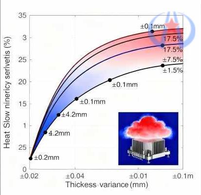
- Direct Impact of Thickness Deviation on Heat Flux: When there is thickness deviation in an aluminum disc, heat flux concentrates in thinner areas (the “heat flux concentration effect”), leading to local overheating. For example, for a 1060 aluminum disc with a designed thickness of 3mm, if the thickness deviation is ±0.02mm, the heat flux deviation rate is only 3.5%; if the deviation increases to ±0.1mm, the heat flux deviation rate rises to 18.2%. Excessively high local heat flux density causes thermal fatigue of the material, further reducing thermal conductivity efficiency.
- FEA Simulation Verification: Simulations of aluminum discs for CPU heat sinks (diameter 50mm, designed thickness 3mm) show:
-
- When the tolerance is ±0.02mm, the deviation of heat flux distribution uniformity is 4.2%, with a maximum temperature rise of 38℃;
-
- When the tolerance is ±0.05mm, the uniformity deviation increases to 9.8%, with a maximum temperature rise of 45℃;
-
- When the tolerance is ±0.1mm, the uniformity deviation reaches 17.5%, with a maximum temperature rise of 52℃.
This indicates that smaller thickness tolerance results in more consistent heat conduction paths and less heat flux loss.
B. Optimizing Interface Contact Pressure Distribution and Reducing Contact Thermal Resistance
- Correlation Between Thickness Tolerance and Contact Pressure: A certain pressure (e.g., 50~100N for heat sink assembly) is required during the assembly of aluminum discs. If there is thickness deviation, pressure concentrates in thicker areas, resulting in insufficient pressure in thinner areas and a decrease in \(h_c\). For example, for an aluminum disc with a thickness deviation of ±0.05mm, the pressure distribution deviation after assembly reaches 35%, and \(h_c\) in thinner areas is only 60% of the designed value; for an aluminum disc with a tolerance of ±0.02mm, the pressure distribution deviation is only 12%, and the \(h_c\) retention rate exceeds 90%.
- Experimental Data Comparison: Contact thermal resistance tests were conducted on 6061 aluminum alloy discs (diameter 80mm, designed thickness 4mm), with the following results:
|
Thickness Tolerance (mm)
|
Contact Pressure (N)
|
Pressure Distribution Deviation (%)
|
Contact Thermal Resistance \(R_{contact}\) (K·m²/W)
|
Relative Thermal Conductivity Efficiency (%)
|
|
±0.02
|
80
|
12
|
0.0008
|
100
|
|
±0.05
|
80
|
35
|
0.0012
|
85
|
|
±0.10
|
80
|
62
|
0.0018
|
72
|
C. Reducing Stress Deformation and Avoiding Interruption of Heat Conduction Paths
- Stress Issues Caused by Uneven Thickness: During the rolling or heat treatment of aluminum discs, excessive thickness deviation leads to internal stress (e.g., internal stress of aluminum discs with a thickness deviation of ±0.1mm can reach 50~80MPa). After assembly, bending deformation is likely to occur, resulting in gaps between the aluminum disc and contact components (gaps >5μm significantly increase thermal resistance).
- Impact of Deformation on Thermal Conduction: The amount of bending deformation is positively correlated with thickness tolerance, as shown in the formula: \(\delta = \frac{k \cdot (\Delta d)^2}{E \cdot d}\)
Where \(k\) is the shape factor (≈0.3), and \(E\) is the elastic modulus of aluminum (70GPa). When \(\Delta d = 0.1mm\) and \(d = 3mm\), \(\delta = 0.021mm\) (21μm), far exceeding the 5μm gap threshold. At this point, the interface thermal resistance increases sharply by 3~5 times.
HW-D. Mechanism of Surface Roughness in Enhancing Thermal Conductivity Efficiency of Aluminum Discs
Surface roughness (Ra) refers to the arithmetic mean value of the microscopic unevenness of a surface (GB/T 1031 stipulates that the common Ra range for aluminum workpieces is 0.025~6.3μm). Its role focuses on regulating interface thermal resistance, with core mechanisms including:
A. Increasing Actual Contact Area and Reducing Interface Thermal Resistance
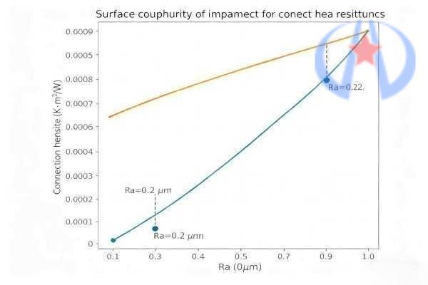
- Quantitative Relationship Between Roughness and Contact Area: The ratio of \(A_{real}/A_{apparent}\) for smooth surfaces (Ra≤0.2μm) can reach 30%~40%, while that for rough surfaces (Ra≥1.0μm) is only 5%~10%. For example, when an aluminum disc with Ra=0.2μm is in contact with a chip, \(A_{real} = 0.35 \cdot A_{apparent}\) and \(R_{contact} = 0.0007K·m²/W\); when Ra increases to 1.0μm, \(A_{real} = 0.08 \cdot A_{apparent}\) and \(R_{contact} = 0.0032K·m²/W\), with thermal resistance increasing by 4.6 times.
- Impact of Micro-Morphology: The “peak-to-valley height” (Rz) of surface micro-unevenness is also critical. For surfaces with the same Ra but different Rz, the difference in \(A_{real}\) can reach 20%~30%. For example, when Ra=0.5μm, the \(A_{real}\) of a surface with Rz=2.0μm is 28% higher than that with Rz=4.0μm, because the peaks and valleys of the former are flatter, enabling more sufficient contact of micro-protrusions.
B. Regulating Surface Oxide Film State and Reducing Oxide Thermal Resistance
- Thermal Resistance Characteristics of Oxide Films: The thermal conductivity of the natural oxide film (Al₂O₃) on the surface of aluminum discs is only 10~15W/(m・K), much lower than that of aluminum (237W/(m・K)). The thickness of the oxide film (usually 5~10nm) is related to roughness:
-
- Smooth surfaces (Ra≤0.2μm): The oxide film is uniform and thin (5~7nm), with oxide thermal resistance \(R_{oxide} = 0.0002K·m²/W\);
-
- Rough surfaces (Ra≥0.8μm): Surface protrusions are prone to preferential oxidation, resulting in an oxide film thickness of 10~15nm with uneven distribution, and \(R_{oxide} = 0.0005K·m²/W\), with thermal resistance increasing by 1.5 times.
- Experimental Verification: Oxide film tests were conducted on 1060 aluminum discs, with the following results:
|
Surface Roughness Ra (μm)
|
Oxide Film Thickness (nm)
|
Oxide Thermal Resistance \(R_{oxide}\) (K·m²/W)
|
Total Interface Thermal Resistance \(R_{total}\) (K·m²/W)
|
Relative Thermal Conductivity Efficiency (%)
|
|
0.1
|
6
|
0.0002
|
0.0009
|
100
|
|
0.5
|
8
|
0.0003
|
0.0015
|
82
|
|
1.0
|
14
|
0.0005
|
0.0032
|
58
|
C. Adapting to Heat-Conducting Media and Optimizing Heat Transfer Efficiency
- Scenarios Without Heat-Conducting Media (e.g., Dry Contact): Ra needs to be minimized (≤0.3μm) to increase \(A_{real}\). For example, aluminum discs used in vacuum equipment require Ra to be controlled within 0.1~0.2μm; otherwise, the dry contact thermal resistance will exceed the design threshold.
- Scenarios With Heat-Conducting Media (e.g., Thermal Grease, Thermal Pads): Roughness must match the particle size of the medium. For example, when the particle size of thermal grease is 5~10μm, Ra should be controlled within 0.5~0.8μm, which not only allows the medium to fill the peak-valley gaps but also prevents excessive medium thickness (excessive thickness increases medium thermal resistance). Experiments show that when Ra=0.6μm is matched with thermal grease of 8μm particle size, \(R_{contact}\) is 25% lower than that with Ra=0.2μm (insufficient medium filling) and 40% lower than that with Ra=1.0μm (excessive medium thickness).
HW-E. Interactive Effects and Collaborative Optimization of Thickness Tolerance and Surface Roughness
A.Mechanism of Interactive Effects
- Thickness Tolerance Dominates Contact Pressure, While Roughness Dominates Contact Area: If the thickness tolerance is too large (>±0.05mm), even if Ra is optimized to 0.2μm, uneven contact pressure distribution will still lead to insufficient local \(A_{real}\), making it difficult to reduce \(R_{contact}\); conversely, if Ra is too large (>0.8μm), even if the thickness tolerance is controlled within ±0.02mm, the small \(A_{real}\) will still cause \(R_{contact}\) to exceed the standard.
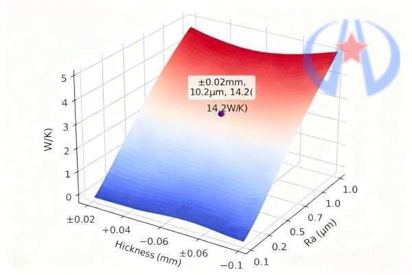
- Quantification of Interactive Effects: Thermal conductivity efficiency tests were conducted on aluminum discs with different parameter combinations (1060 pure aluminum, diameter 60mm, designed thickness 3mm), with the following results:
|
Thickness Tolerance (mm)
|
Surface Roughness Ra (μm)
|
Contact Pressure Distribution Deviation (%)
|
Actual Contact Area Ratio (%)
|
Total Thermal Conductivity Efficiency (W/K)
|
Efficiency Improvement Potential (%)
|
|
±0.02
|
0.2
|
12
|
38
|
14.2
|
100 (Baseline)
|
|
±0.02
|
0.8
|
13
|
15
|
9.8
|
69
|
|
±0.10
|
0.2
|
65
|
22
|
8.5
|
60
|
|
±0.10
|
0.8
|
68
|
8
|
5.3
|
37
|
B. Scenario-Specific Collaborative Optimization Strategies
- Electronic Heat Sink Scenarios (e.g., CPU, LED):
-
- Core Requirements: Low interface thermal resistance, high heat flux uniformity;
-
- Optimized Parameters: Thickness tolerance ±0.02~±0.03mm (GB/T 3880.3 High-Precision Grade), Ra=0.1~0.3μm (electropolishing process);
-
- Supporting Measures: Use thermal grease (particle size 5~8μm) to fill micro-gaps, further reducing \(R_{contact}\).
- Cookware Heating Plate Scenarios (e.g., Rice Cookers, Induction Cookers):
-
- Core Requirements: Heating uniformity, wear resistance;
-
- Optimized Parameters: Thickness tolerance ±0.03~±0.05mm (balancing cost and uniformity), Ra=0.3~0.5μm (precision grinding process);
-
- Supporting Measures: Surface anodization (film thickness 5~8nm) to protect the surface while avoiding excessive oxide thermal resistance.
- New Energy Battery Thermal Management Scenarios (e.g., Power Battery Cooling Plates):
-
- Core Requirements: High thermal conductivity, corrosion resistance;
-
- Optimized Parameters: Thickness tolerance ±0.03~±0.04mm, Ra=0.2~0.4μm (chemical polishing process);
-
- Supporting Measures: Surface coating with thermal silica gel (thickness 10~20μm) to adapt to the contact requirements of battery tabs.
HW-F. Verification of Typical Application Cases
A. Optimization Case of Aluminum Discs for CPU Heat Sinks
- Original Parameters: 6061 aluminum alloy, thickness 3mm, tolerance ±0.08mm, Ra=0.8μm;
- Optimized Parameters: Tolerance adjusted to ±0.02mm (controlled by four-high cold rolling mill), Ra reduced to 0.2μm (electropolishing);
- Test Results:
-
- Interface thermal resistance decreased from 0.0021K・m²/W to 0.0009K・m²/W, a reduction of 57%;
-
- CPU full-load temperature rise decreased from 55℃ to 42℃, a reduction of 24%;
-
- Heat flux uniformity deviation decreased from 16% to 4.5%, meeting the heat dissipation requirements of Intel Core i7 processors.
B. Optimization Case of Aluminum Discs for Induction Cooker Heating Plates
- Original Parameters: 1060 pure aluminum, thickness 4mm, tolerance ±0.1mm, Ra=1.0μm;
- Optimized Parameters: Tolerance adjusted to ±0.05mm (high-precision rolling), Ra reduced to 0.4μm (precision grinding);
- Test Results:
-
- Heating uniformity deviation decreased from 18% to 7%, meeting the requirement of “heating uniformity ≤10%” in GB 4706.29-2008;
-
- Thermal efficiency increased from 85% to 92%, saving 0.12 kWh per hour;
-
- Surface oxide film thickness decreased from 15nm to 8nm, a reduction of 47% in oxide thermal resistance.
HW-G. Conclusions and Prospects
Thickness tolerance and surface roughness of aluminum discs play key roles as “path guarantee” and “interface optimization” in enhancing thermal conductivity efficiency: Thickness tolerance reduces heat flux loss and deformation risks by controlling the consistency of heat conduction paths and contact pressure distribution, with an optimization contribution of 8%~15%; surface roughness reduces interface thermal resistance by increasing the actual contact area and regulating the oxide film state, with an optimization contribution of 12%~20%. Their collaborative effect can improve thermal conductivity efficiency by 30%~40%.
Future development directions should focus on: 1. High-precision manufacturing processes (e.g., real-time control of thickness tolerance to ±0.01mm using laser thickness gauges, achieving Ra≤0.05μm via magnetorheological polishing); 2. Intelligent parameter matching (automatically recommending thickness tolerance and roughness combinations based on application scenarios using AI algorithms); 3. Surface functional modification (e.g., reducing oxide film thermal resistance with nanocoatings while maintaining low roughness), to further break through the bottleneck of aluminum disc thermal conductivity efficiency.